One of the questions that a lot of our UCS customers ask us is “What is the difference between Update Firmware and Active Firmware?”
Tag Archives: cisco
Cisco UCS 1.4 Post Upgrade Warnings
After upgrading our UCS lab to 1.4 all of my Service Profiles and Service Profile Templates were in a warning state with blue boxes around them. There wasn’t an outage and all of our blades were still functioning.
The warnings were due to they way Cisco changed the Serial over LAN Policy. My current Service Profile Template had the Serial over LAN Policy set to <Not Set> but in 1.4 that isn’t a valid option. I changed the Serial over LAN Policy to “No Serial over LAN Policy” and all of the warnings disappeared.
Cisco UCS Firmware 1.4
I have to say now that I have had a chance to implement Cisco UCS firmware 1.4 and look at the new features I am blown away. Cisco should have made this version 2.0.
Here is a list of my favorite new features included in 1.4:
SAN Port Channeling:
This allows you to bundle all of the FC connections on a 6120 so that there is 1 logical uplink to the northbound FC switch. Port channels provide faster convergence when there is link failure because a server vHBA doesn’t have to get re-pinned to another uplink.
Maintenance Policies:
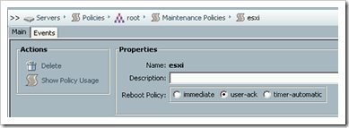
Remember when making a change on a Service Profile rebooted the server without asking? Or even worse making a change on an updating Service Profile template caused all of the Service Profiles bound to that template to reboot?
Well Maintenance Policies prevent these unplanned reboots by forcing the user to acknowledge the reboot or you can even schedule it to happen after hours.
Policy Usage Reporting:
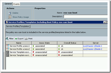
Ever wondered what Service Profiles and Service Profile templates were using one of the many UCS policies? Well wonder no more there is now a Show Policy Usage report on every policy in UCSM. I wish there was a similar feature for templates, I am guessing that will be included in a future update.
Enhanced Active Directory Support:
You no longer have to extend the Active Directory schema and you can map UCS roles to Active Directory groups.
Multiple Authentication Sources:
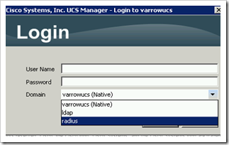
Pre-1.4 you could only have one authentication source at a time. Now you can create authentication domains and have the option to login to all of them.
Local File System Download Option:
A remote SCP, SFTP server is no longer required for downloading new firmware or saving backups.
There are lots of other new features in 1.4 that I didn’t mention here, these were just some of my favorites.
Cisco UCS Service Profile Coolness
Last week I did a Cisco UCS project that included building out a new VMware vSphere ESXi 4.1 cluster using the new UCS blades. Now that ESXi boot from SAN is supported we used 5GB boot LUNs for the install.
During the course of the install the customer stated that in a few weeks they will be purchasing another chassis of blades and will be using these for additional ESXi 4.1 hosts. To demonstrate the power of the UCS stateless model I went ahead and provisioned all 8 of the new ESXi hosts even though the hardware did not exist.
Sounds like a magic trick right? Well sort of, but using the power of UCS Service Profiles and boot from SAN here is how we accomplished this:
- Built out the UCS Service Profiles for the hosts from the Service Profile template.
- Put 4 of the new ESXi hosts into maintenance mode and powered them down.
- Disassociated the service profiles from those 4 blades.
- Using these 4 free blades we associated them with 4 of the Service Profiles for the hardware that did not yet exist.
- Created the boot LUNs
- Installed ESXi 4.1.
- Added the hosts to vCenter.
- Applied our vSphere Host Profile to configure the new hosts.
- Powered down the 4 new servers.
- Pre-built the next 4 the same way.
- Powered those down and associated the original service profiles with the 4 blades.
Now when the customers gets the new chassis and blades all they have to do is associate the service profiles and they are done.
Cisco UCS vNIC/vHBA Placement policies
I recently have had a few people ask me what Cisco UCS adapter placement policies are used for and how/when to use them. This post will hopefully answer those questions and give a few examples.
First I will start with the Cisco definition of what vNIC/vHBA placement policies are. This definition was copied from the Cisco UCS Manager GUI Configuration guide – Cisco UCS GUI Configuration Guide
vNIC/vHBA placement policies are used to assign vNICs or vHBAs to the physical adapters on a server. Each vNIC/vHBA placement policy contains two virtual network interface connections (vCons) that are virtual representations of the physical adapters. When a vNIC/vHBA placement policy is assigned to a service profile, and the service profile is associated to a server, the vCons in the vNIC/vHBA placement policy are assigned to the physical adapters. For servers with only one adapter, both vCons are assigned to the adapter; for servers with two adapters, one vCon is assigned to each adapter.
You can assign vNICs or vHBAs to either of the two vCons, and they are then assigned to the physical adapters based on the vCon assignment during server association. Additionally, vCons use the following selection preference criteria to assign vHBAs and vNICs:
- All
The vCon is used for vNICs or vHBAs assigned to it, vNICs or vHBAs not assigned to either vCon, and dynamic vNICs or vHBAs.
- Assigned-Only
The vCon is reserved for only vNICs or vHBAs assigned to it.
- Exclude-Dynamic
The vCon is not used for dynamic vNICs or vHBAs.
- Exclude-Unassigned
The vCon is not used for vNICs or vHBAs not assigned to the vCon. The vCon is used for dynamic vNICs and vHBAs.
For servers with two adapters, if you do not include a vNIC/vHBA placement policy in a service profile, or you do not configure vCons for a service profile, Cisco UCS equally distributes the vNICs and vHBAs between the two adapters
Usage Scenarios
Half-width Blades (B200-Mx)
If you have half-width blades (B200-Mx) then you will only ever have a single mezzanine card or vCon1. In this case you would only use a vNIC/vHBA placement policy in these two scenarios:
- In a VN-Link in hardware configuration and you are attaching a Dynamic vNIC Connection Policy to the service profile. In this scenario a vNIC/vHBA Placement Policy is required so that the dynamic vNICs get assigned after the non-dynamic vNIC/vHBAs. This guarantees that the ESX vmnics and HBAs are at the top of the PCI numbering and that some of the dynamic vNICs aren’t intermixed. Here is a screen shot of this configuration, anything not assigned (dynamic vNICs) are placed below the assigned vNICs/vHBAs.

- To force the PCI numbering of the NICs/HBAs as seen by the operating system. If you wanted to make sure the HBAs were seen before the NICs or vice versa you could do that with a placement policy.
Full-width Blades (B250-Mx, B440-M1)
- Use a placement policy to evenly distribute vNICs and vHBAs across 2 mezzanine cards (vCon1 and vCon2). Here is a screen shot of this configuration,

- You have two different type of mezzanine cards; Cisco UCS VIC M81KR (aka Palo) and Cisco CNA M71KR (aka Menlo). Lets say for compatibility reasons you want all vNICs on the Palo and all vHBAs on the Menlo. In this scenario would create a placement policy to configure this assignment. Here is a screen shot of this configuration,
- In a VN-Link in hardware configuration and you are attaching a Dynamic vNIC Connection Policy to the service profile and you want all of the Dynamic vNICs to be on one adapter and regular vNICs/vHBAs to be on the other.

- You have two different types of mezzanine cards; Cisco UCS VIC M81KR (aka Palo) and Cisco CNA M71KR (aka Menlo) and you are configuring VN-Link in hardware. Lets say for compatibility reasons you want all vNICs on the Palo and all vHBAs on the Menlo. In this scenario would create a placement policy to configure this assignment. Here is a screen shot of this configuration,
It is important to note that only the Cisco UCS VIC M81KR (aka Palo) allows you to have more than 2 vNICs/vHBAs per adapter and is the only card that allows for VN-Link in hardware where you have up to 54 Dynamic vNICs that are dynamically assigned to VMs that are configured to be part of the UCSM Managed Distributed Virtual Switch. – VN-Link in Cisco UCS
Cisco UCS Ethernet Frame Flows
In this post I am going to walk through the northbound frame flows in the Cisco UCS system. Hopefully this information will help you better understand UCS networking.
In other posts I will walk through the southbound and maybe east-west frame flows. I am breaking the posts down into multiple posts to make it easier for the reader to get through and understand.
I learned most of the information in this post from the Cisco Live 2010 session “Network Redundancy and Load Balancing Designs for UCS Blade Servers” presented by Sean McGee of Cisco. Some of the diagrams in this post were also taken from that same session.
Acronyms used in this post:
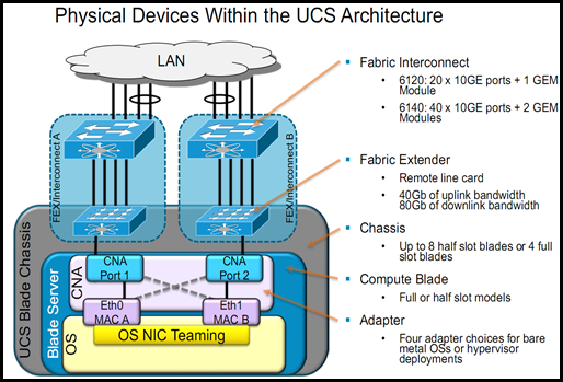
CNA – Converged Network Adapters on the mezzanine card
FEX – Fabric Extender 2104XP that lives in the chassis. There are usually two of these per chassis, one for Fabric A and on for Fabric B.
FI = Fabric Interconnect, the 6120s/6140s. Usually deployed as a pair in an HA configuration.
IOM – I/O Module, another name for the FEX.
First lets take a look at the physical components within the UCS System. Below is a logical and physical diagram of the components that make up UCS.
Now lets take a look at northbound frame flows. The following diagram lists the decision points that take place as the frame travels from the OS up through and out of UCS to the LAN.
First we will start with the northbound traffic leaving from the Operating System.
- OS creates the frame – The happens the same way in UCS as is it does in any other hardware.
- The OS then has to decide which PCIe Ethernet interface to forward the frame out of. If there multiple PCIe Ethernet interfaces the OS NIC teaming software decides which interface to use based on a hashing algorithm or a round robin mechanism. In the case of VMware and the VIC (Palo) this could be from 1 to 58 choices, realistically you probably will have less than 10.
- If there is just 1 PCIe interface and Fabric Failover is enabled then it is the UCS Menlo ASIC that makes the frame forwarding decision.
After the frame has entered the physical mezzanine CNA another decision must be made as to which one of the 2 physical CNA ports are used to send the frame to the FEX. This decision depends on how the vNIC was configured in UCSM. When configured a vNIC as part of a Service Profile in UCSM you must choose which fabric to place this vNIC on (A or B) and whether or not Fabric Failover is enabled. The screen shot below shows these configuration options.
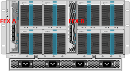
With this configuration Fabric A will be used unless for some reason it is down and then Fabric B will be used because Fabric Failover is enabled. For the purpose of this post we will assume the frame is exiting CNA Port 1 that is physically pinned to FEX (Fabric Extension Module in the back of the chassis) 1 on the mid-plane of the chassis. FEX 1 is the left hand FEX as you are looking at the back of the chassis, see the diagram below.
The FEX have 8 10GE KR back-end mid-plane ports or traces and 4 front-end 10GE SFP+ ports. The picture below shows the 8 back-end ports and the 4 front-end ports on a FEX. The 8 back-end ports are not physically visible like the picture shows this is just a good picture that logically shows the ports.
The back-end FEX port that the frame goes across depends on which blade this particular OS is running on. In our example we will say blade 3. There is a blade CNA port to FEX back-end port pinning that happens. For blade 3 CNA 1 the back-end FEX port will be port 3 or Eth1/1/3.
Eth X/Y/Z where
- X = chassis number
- Y = mezzanine card number or CNA number
- Z = FEX (IOM) port number
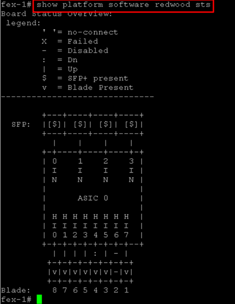
Below is a screen shot of the output of the cmd “show platform software redwood sts”. This command must be executed from the fex-1# context. To get here from the UCSM cli prompt first type “connect local-mgmt” then “ucs-A(local-mgmt)# connect iom 1” The 1 in this cmd is the chassis number.
Once the frame is in the FEX it has to be forwarded to the Fabric Interconnect across one of the 4 front-end 10GE SFP+ ports. The port the frame goes across depends on how many FEX to Fabric Interconnect cables are connected and which blade it originally came from. There is a blade to IOM uplink pinning that happens based on the number of uplinked SFP+ ports. This pinning is not user controllable.
Here is a table and diagram showing how the pinning works in the three different uplink options.
| 1 IOM-FI Cable | 2 IOM-FI Cables | 4 IOM-FI Cables |
| All blades CNA 1 goes out this one cable, 8:1 oversubscription | slots 1,3,5,7 are pinned to one uplink and slots 2,4,6,8 are pinned to the other, 4:1 oversubscription | slots 1,5 out 1 slots 2,6 out 2 slots 3,7 out 3 slots 4, 8 out 4 |
For our example there are 4 IOM-FI uplinks.
So to summarize the path the frame has traveled up to this point.
- OS generated frame.
- OS chose the PCIe Ethernet Interface using either NIC teaming software. In our case there was only one PCIe Ethernet vNIC assigned to the Service Profile on this blade.
- Frame was forwarded to CNA 1 because we set Fabric A as the preferred fabric unless it is down. The Fabric Failover ASIC chose CNA 1 because Fabric A is up.
- CNA 1 is pinned to IOM 3 because it is blade 3.
- The uplink IOM SFP+ port 2 was used to forward the frame to Fabric Interconnect A because it is blade 3 and there are 4 SFP+ uplinks connected from IOM-FI.
The next step is for Fabric Interconnect A to forward this frame to a northbound L2 LAN switch. Before this can happen the FI has to determine which northbound Ethernet port to send it out of. This decision process is as follows
- Are there any LAN Pin Groups? If manual pinning is configured for this blade’s vNIC 1 to go out a specific uplink or Port Channel then that port or Port Channel is used to forward the frame. If it is Port Channel then the specific interface of the Port Channel that is used is based on the Port Channel hashing algorithm.
- Are Port Channels in use? If it is Port Channel then the specific interface of the Port Channel that is used is based on the Port Channel hashing algorithm.
If there are no LAN Pin Groups or Port Channels then automatic pinning is used in a round robin fashion. If there are 8 blades in the chassis and 4 northbound Ethernet uplinks then there will be 2 blades pinned to each uplink. This works in much the same way the default VMware vSwitch teaming works if you familiar with that.
So I think that about covers the northbound Ethernet frame flows. I stated earlier I will be posting the corresponding south, west and east flows in follow on posts.
Cisco UCS Enhancements in Firmware 1.3
Cisco UCS firmware 1.3 was released last week. There are lots of new features in this latest update and Dave Alexander (ucs_dave) outlined most of those in his blog post – http://www.unifiedcomputingblog.com/?p=151
What I will be covering here are the features that Dave didn’t cover nor were they mentioned in the release notes for 1.3 – http://www.cisco.com/en/US/docs/unified_computing/ucs/release/notes/ucs_22863.html
The feature I was most excited about was the advanced BIOS settings control from the Service Profile.
I updated our UCS lab this morning and on the the first login to UCSM after I finished the update I was surprised to see the Fabric Interconnects now have listed in their name what their current cluster role is. Before you had to drill down into each one to see this.
The next change I noticed was that the BMC had been renamed to CIMC (Cisco Integrated Management Controller). I personally like the new name better because I think it makes more since than BMC.
I was then looking around in the Admin tab and noticed a new section labeled Capability Catalog. The UCSM GUI Configuration Guide for 1.3 states this about the catalog
“The capability catalog is a set of tunable parameters, strings, and rules. Cisco UCS Manager uses the catalog to update the display and configurability of components such as newly qualified DIMMs and disk drives for servers.”
The catalog also has an Update Catalog function that can be used to update as Cisco updates it.
On the VM tab there is a new “Configure VMware Integration” wizard to assist in configuring VN-Link in hardware. (this requires the VIC adapter in the server blades and VEM installed on the ESX hosts)
Here are a few screen shots of the new BIOS settings that can be configured. These new settings are implemented via a BIOS Policy that is then tied to a Service Profile or Service Profile Template.
I am sure there may be a few more hidden gems in here but these are the ones I have noticed so far.
Cisco UCS Server Pools: Configuration
In my previous post I discussed Cisco UCS Server Pools and use cases. In this post I will be walking through the configuration of Server Pools, Server Pool Policies and Server Pool Policy Qualifications.
As stated in my previous post one of the use cases for Server Pools is in the server farm model where you have varying amounts of RAM and CPUs in your blades and and you want a way to efficiently deploy a farm of web server, ESX hosts and database servers without having to specifically choose a server blade.
In this configuration example I will walk through the configuration on an auto-populated Server Pool using Server Pool Policies and Server Pool Policy Qualifications.
The first step is to create a Server Pool. To do this go to the Servers tab, Pools.
Right-click on Server Pools to create a new pool
On the add server page temporarily add a blade and then remove it. If you don’t do this the Finish button stays grayed out. This is one of the UCSM nuances.
The next step is to create a Server Pool Policy Qualification
I am going to create a web server qualification that uses a Memory Qualification for 8 GB RAM
Now to tie it all together with a Server Pool Policy
To use this new auto-populating Server Pool associate a Service Profile Template to is so that when you deploy new Service Profiles from the template you don’t have to select a blade, it will be automatically selected if there is one available in the associated pool.
One important note is that if your blades have already been discovered you will need to re-acknowledge them before they will be added to a server pool.
Another important note is that if you re-acknowledge a blade it will reboot it without asking so you probably only want to re-acknowledge blades that are not associated with a Service Profile.
Cisco UCS Server Pools: Use Cases
This is a a two part blog post on Cisco UCS Server Pools. This first post will focus on what Server Pools are and use cases and the next post will focus on configuration.
Cisco UCS Server pools are one of the more mysterious features of UCS. I say mysterious because in my opinion the usage and configuration of them is not very intuitive. Let’s start with Cisco’s definition of a Server Pool, this definition was copied from the Cisco UCS Manager GUI Configuration Guide, Release 1.2(1) found here – http://www.cisco.com/en/US/products/ps10281/products_installation_and_configuration_guides_list.html
“A server pool contains a set of servers. These servers typically share the same characteristics. Those characteristics can be their location in the chassis, or an attribute such as server type, amount of memory,local storage, type of CPU, or local drive configuration.”
You are probably thinking that doesn’t sound very mysterious and you are right it doesn’t until you start digging into the use cases and configuration of Server Pools.
Here are some characteristics of a Server Pool:
- Can be manually populated or auto-populated
- Manual is where you select the blades that you want to be part of a given pool.
- Auto-populated works by creating Server Pool Qualifications and Server Pool Policies where you define the specific hardware characteristics and based on that the blades are placed into one pool or another.
- A blade can be in multiple pools at the same time – For example lest say you have a multi-tenancy UCS environment and multiple Server Pools have the same blades in them. The blades are not actually tied to a specific organization in UCS and so when a user deploys a new service profile and uses a Server Pool for the assignment they will grab the next available server in their pool. This blade could have also been in any other Server Pool in any other UCS organization that met the qualification. It works on a first come first serve model. Once a blade is associated with a Service Profile is not available to any
- A service profile template or service profile can be associated with a Server Pool for rapid blade deployments
- A blade can be located in any chassis that is management by the UCS Cluster
Server Pool Use Cases
Server Farm Model – In this model you have an environment made up of varying applications that have varying hardware requirements.
For example:
- Web server farm that needs at least 8 GB RAM and 1 quad core CPU.
- Database server farm that needs at least 32 GB RAM and 2 quad core CPUs.
- An ESX server farm that needs at least 48 GB RAM, 2 quad core CPUs and a Cisco UCS VIC M81KR adapter.
Rapid Deployments – This would be a new UCS implementation where you are wanting to deploy new blades as fast and efficiently as possible without have to select specific blades to associate Service Profiles with.
How to Enable CDP On Cisco UCS vNICs
If you are familiar with managing VMware ESX 3.5/4.x in an environment that includes Cisco LAN switches then you have probably used “CDP listen state” that is enabled by default on an ESX install. To view this information in vCenter select an ESX host, go to the configuration tab in the right pane, select the Networking link and then click on the little blue call out box next to a vmnic that is uplinked to a vSwitch. A pop-up window opens displaying the CDP information. The information can be invaluable when troubleshooting networking issues. You can determine which switch/switch port the NIC is plugged into, native VLAN and other useful information. This is also a great way to verify that your vSwitch uplinks are going to 2 different physical switches (if you have that option).
As I stated earlier the default CDP configuration on an ESX vSwitch is the listen only state. I have found that the network engineers find it very useful if you configure CDP to advertise as well. When you enable this on a vSwitch the network engineer can issue the “show cdp neighbors” command from the IOS command line and witch switch ports each ESX vmnic is plugged into. This can also be very useful when you and the network engineer are troubleshooting network issues with ESX.
To configure CDP to advertise run this command from the ESX console or from an SSH session.
“esxcfg-vswitch -B both vSwitch0”
To check the state of the CDP configuration run this command..
“esxcfg-vswitch -b vSwitch0”
Note – you must enable CDP on all vSwitches if you want to see every vmnic from the switch side.
If you are using a VMware vNetwork Distributed Switch then you can configure the CDP state from the vCenter GUI. To do this go to the edit settings on the dvSwitch and then go to Advanced.
Ok, now to the point of configuring all of this on Cisco UCS blades.
By default the vNICs in Cisco UCS have CDP listen and advertise turned off. You can see this from an ESX host that is running on a UCS blade by clicking on the little blue call out box. When the pop-up opens it states that Cisco Discovery Protocol is not available.
To enable CDP the first thing you must do is to create a new Network Control policy. To do this go to the LAN tab in UCSM, expand Policies, right-click Network Control Policies to create a new policy. Name it something like “Enable-CDP” and select the option to enable CDP.
The next step is to apply the new policy to the ESX vNICs. If you are using updating vNIC templates then all you need to do is go to each vNIC template for your ESX vNICs select the new policy from the Network Control Policy drop down. If you are not using vNIC templates but you are using an updating Service Profile Template then you can enable it there. If you are using one-off Service Profiles are a non-updating Service Profile then you must go to every Service Profile and enable this new policy on every vNIC.
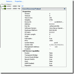
Now when you click the call-out box you should see the CDP information coming from the Fabric Interconnect that you are plugged into.


